UPS-MON — JBus/Modbus RTU UPS telemetry with ESP32
Motivation and objectives
Following repeated mains outages that took the home lab down mid-flight, a line-interactive Socomec NETYS PR 2200 (NPR-2200-RT) UPS was installed to bridge brownouts and enable graceful shutdowns. The batteries were replaced with six new 12 V blocks (72 V bus, ≈82.1 V float), after which the unit ran to spec — but remained operationally opaque. A UPS is a black box until the day it matters.
The unit's rear-panel DB9 RS-232 service port offered a path to full observability. The project set four objectives:
- Full-coverage telemetry — implement every register the official protocol documentation exposes: measurements, states, alarms, configuration and commands.
- Integration — publish to the existing MQTT-based monitoring stack with zero changes on the broker side.
- Autonomous notification — deliver outage and alarm events to a phone without operating any server.
- Reproducibility — document the hardware adapter so it can be rebuilt from off-the-shelf parts.
System architecture
NETYS PR 2200 ──RS-232 (DB9)──▶ MAX3232 ──3.3 V TTL──▶ ESP32 WROOM-32
                                                       │
              ┌────────────────────────────────────────┼───────────────┐
              ▼                                        ▼               ▼
        MQTT broker                              FCM (HTTPS)     BLE (NUS)
   (Shelly-compatible                     push, JWT signed     Android app
    attribute topics)                      on-device           (dashboard,
                                                 │               config,
                                                 ▼               console)
                                              phone
The ESP32 polls the UPS every 15 s, publishes nine MQTT attributes, evaluates state/alarm edges, and — on an outage or alarm — signs an OAuth2 JWT and delivers a push notification directly to Firebase Cloud Messaging. An optional SSD1306 OLED provides a local readout.
Recreating the RS-232 adapter
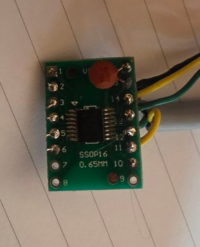
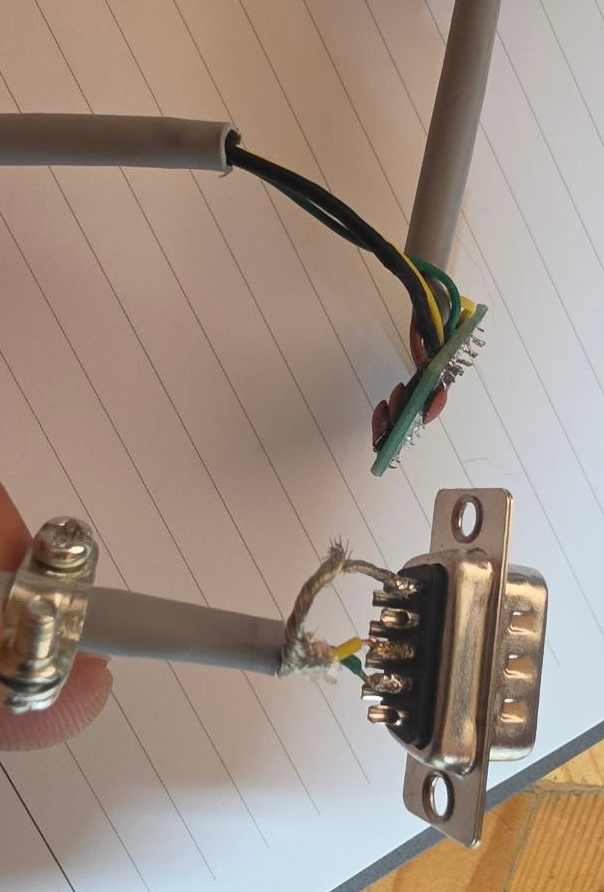
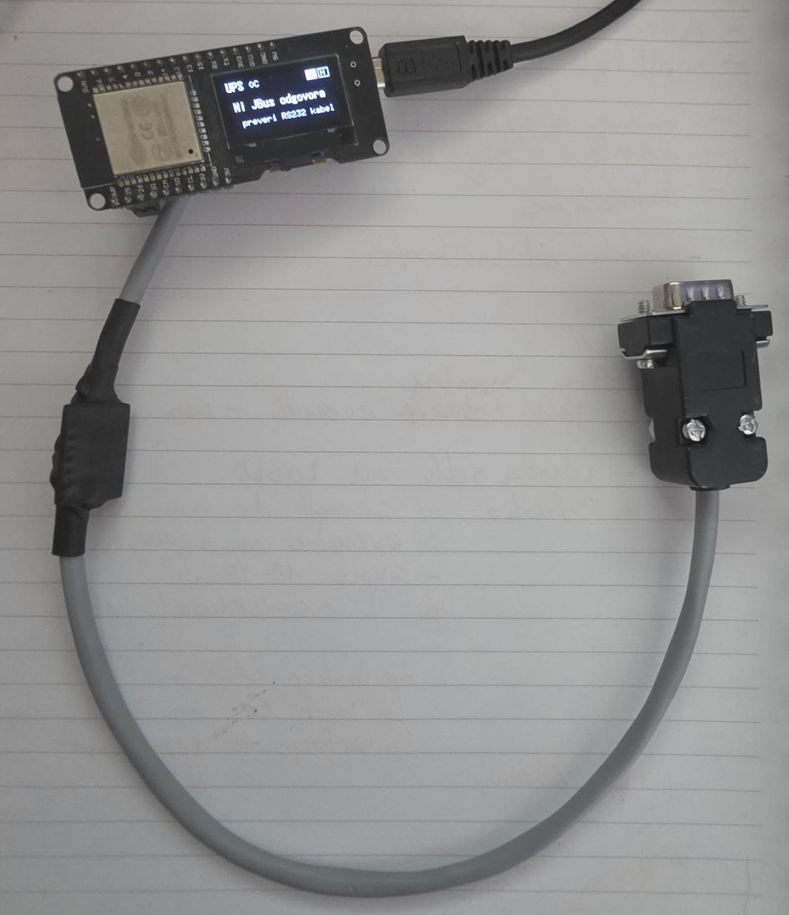
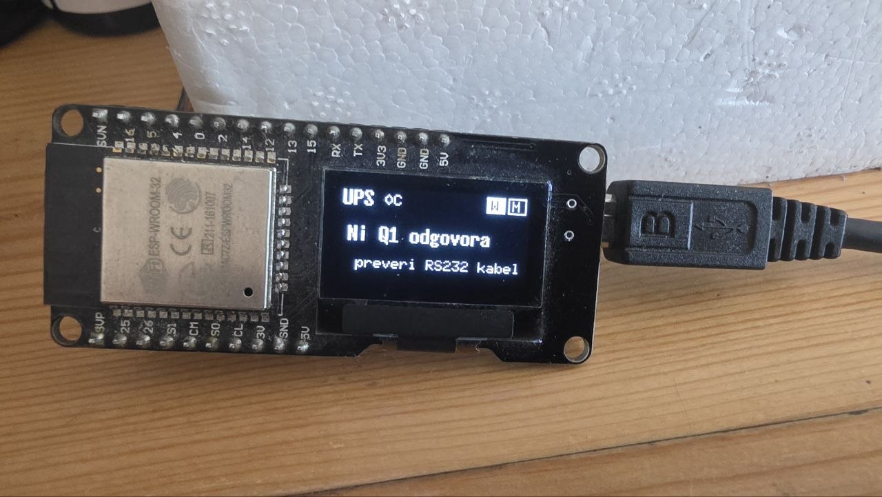
Two build variants are documented. Variant A uses a ready-made MAX3232/SP232 breakout with a DB9 male connector that plugs directly into the UPS. Variant B is a bare MAX3232 (TI, SOIC-16) soldered onto an SSOP16 adapter — smaller, and the one photographed above.
Bill of materials (Variant B)
| Part | Qty | Notes |
|---|---|---|
| MAX3232 (TI), SOIC-16 | 1 | RS-232 ↔ 3.3 V TTL transceiver |
| SSOP16 adapter board | 1 | |
| Ceramic capacitor 0.1 µF | 5 | C1–C4 charge pump, C5 VCC bypass |
| DB9 female connector or cut cable | 1 | only pins 2, 3, 5 are used |
| ESP32 devkit (WROOM-32 / Lolin32 / C6) | 1 | any 3.3 V ESP32 board |
| SSD1306 OLED (optional) | 1 | lolin32 build: SDA=5 / SCL=4 |
Wiring
| From | To |
|---|---|
| UPS DB9 pin 2 (UPS TX) | MAX3232 R1IN (pin 13) |
| UPS DB9 pin 3 (UPS RX) | MAX3232 T1OUT (pin 14) |
| UPS DB9 pin 5 (GND) | MAX3232 GND (pin 15) + ESP32 GND |
| MAX3232 R1OUT (pin 12) | ESP32 GPIO25 (UPS_RX) |
| MAX3232 T1IN (pin 11) | ESP32 GPIO26 (UPS_TX) |
| MAX3232 VCC (pin 16) | ESP32 3V3 — never 5 V |
| MAX3232 T2IN (pin 10) | GND (channel 2 unused) |
| C1, C2 | across C1+/C1− (pins 1/3) and C2+/C2− (pins 4/5) |
| C3, C4 | from V+ (pin 2) and V− (pin 6) |
| DB9 pins 1, 4, 6, 7, 8, 9 | leave unconnected |
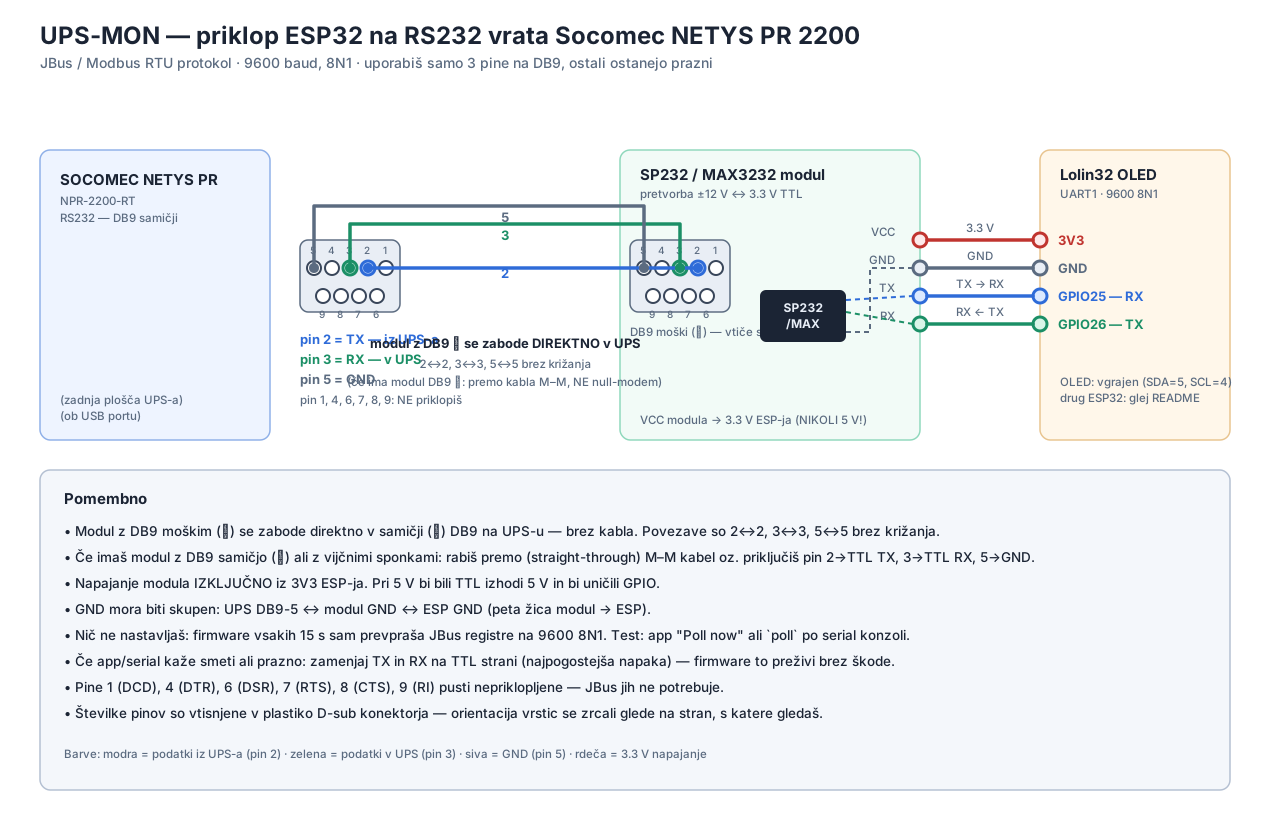
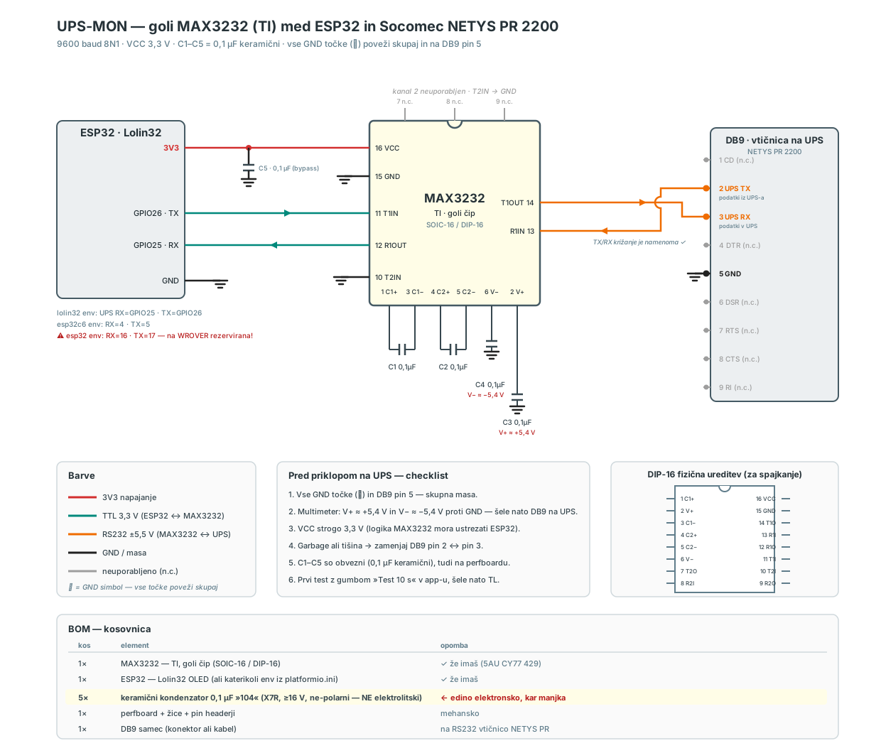
Build checkpoints: the MAX3232 charge pump should produce V+ ≈ +5.4 V and V− ≈ −5.4 V; the TX/RX crossover between the DB9 and TTL sides is intentional.
Serial and firmware configuration
| Parameter | Value |
|---|---|
| Baud rate | 9600 |
| Framing | 8N1 |
| Flow control | none |
| Modbus slave address | 1 |
| Poll period | 15 s (configurable) |
| PlatformIO env | Board | UPS_RX | UPS_TX | Notes |
|---|---|---|---|---|
| lolin32 (tested) | Lolin32 OLED | GPIO25 | GPIO26 | SSD1306 on SDA=5/SCL=4 |
| esp32c6 (default) | ESP32-C6 devkit | GPIO4 | GPIO5 | |
| esp32 | WROOM-32 devkit | GPIO16 | GPIO17 | WROVER/PSRAM: 16/17 reserved — rewire |
Build and flash with pio run -e lolin32 -t upload; provision WiFi/MQTT over BLE from the Android app or setup.html.
Variant A notes: the module's DB9 male plugs straight into the UPS — straight-through wiring (2↔2, 3↔3, 5↔5), no null-modem cable. Power the module exclusively from the ESP32's 3V3 rail; at 5 V the TTL side would output 5 V and damage the GPIOs. The single most common build error is a swapped TX/RX pair on the TTL side.
Protocol: JBus / Modbus RTU
The port does not speak the Megatec/Q1 ASCII protocol common on budget UPSes — an assumption that cost one full firmware rewrite. Per Socomec's "JBUS/MODBUS for NETYS PR – NETYS RT – ITYS" manual (ref. IOM-2003-12), the port implements JBus, Socomec's Modbus RTU derivative:
- Link layer: RS-232, 9600 baud, 8N1, request/response, slave address 1.
- Function codes: 0x03 (read holding registers), 0x10 (write multiple registers).
- Error detection: CRC-16 — polynomial 0xA001, init 0xFFFF, low byte transmitted first — per the Modbus RTU specification.
- Addressing: absolute register addresses at base 0x1000; one register = one 16-bit word.
Frame layout for a register read (fc 0x03):
request:  [addr=01][fc=03][reg_hi][reg_lo][cnt_hi][cnt_lo][crc_lo][crc_hi]
response: [addr=01][fc=03][byte_count][data …][crc_lo][crc_hi]
Register map
| Block | Address | Words | Content |
|---|---|---|---|
| Identity | 0x1000 | – | model id 29 (0x001D), serial NET020-HE, comm fw 2.00 (as measured on this unit) |
| States S00–S47 | 0x1020 | 3 | bit-packed status, LSB-first per word |
| Alarms A00–A63 | 0x1040 | 4 | bit-packed alarms, LSB-first per word |
| Measurements M00–M33 | 0x1060 | 34 | scaled 16-bit integers |
| Nominal/config T00–T28 | 0x10E0 | 29 | ratings, battery Ah, comm fw, input mode |
| Stand-by schedule | 0x1580 | 5 | delayed output-off + automatic restore |
| Battery-test schedule | 0x15A0 | 2 | periodic self-test interval |
| Command word | 0x15B0 | 1 | command execution (fc 0x10) |
| Command control table | 0x15C0 | – | per-command enable bits (gated by state S42) |
Measurements (subset used by the firmware)
| Index | Quantity | Scaling | Use |
|---|---|---|---|
| M03 | total load | % | load attribute |
| M04 | battery state of charge | % | soc attribute (preferred source) |
| M09 | output voltage | V | output_v attribute |
| M15 | output current | A × 10 | not reported by this unit (0xFFFF) |
| M18 | input frequency | Hz × 10 | freq attribute |
| M20 | battery voltage | V × 10 | batt_v attribute |
| M22 | internal temperature | °C | temp attribute |
| M23 | remaining backup time | min (0xFFFF = on mains) | runtime_min |
| M33 | input mains voltage | V | input_v attribute |
Because M15 is not implemented on this unit, real output power is unavailable; the firmware publishes an apparent-power estimate (load % × nominal 2200 VA) instead.
States and alarms
The state words encode mains presence (S00), inverter/bypass/battery selection (S03–S05), stand-by (S08), buzzer (S09), battery-test status (S10/S13/S14), battery condition (S15–S17) and charger activity (S27). The alarm words expose 64 discrete conditions: A01 battery failure, A02 overload, A07 overtemperature, A31 imminent stop — and A60, fan failure. Notably, no fan-speed register exists anywhere in the map: the protocol provides no continuous condition monitoring of the fan, only a binary post-failure indication.
Commands and schedules
| Code | Value | Effect |
|---|---|---|
| C05 / C06 | 0x0005 / 0x0006 | output off (stand-by) / on |
| C07 / C08 / C14 | 0x0007 / 0x0008 / 0x000E | buzzer on / off / disabled |
| C13 | 0x000D | mimic-panel LED test |
| C16 | 0x0010 | immediate battery test (runs ≈7 s; no duration parameter, no cancel) |
Commands execute only when enabled in the control table 0x15C0 (S42 = 1 on this unit). The stand-by schedule (0x1580) implements the graceful-shutdown pattern — output off after a 20–600 s delay, automatic restore after 1–9999 min — written as 32-bit little-endian word pairs. A periodic battery-test schedule (0x15A0, interval in days) completes the command surface.
Empirical device constraints
Three behaviours, undocumented in the manual, were characterised empirically and now shape the firmware:
- Reply truncation. Responses longer than ≈62 bytes are cut and fail CRC. The firmware therefore reads in chunks of ≤8 registers.
- Port lock-up on bus contention. If the line ever sees garbage — e.g. two RS-232 drivers active on one wire — the port stops responding, and no software sequence recovers it; only a full UPS power-cycle (off, mains removed ≈20 s, on) does. Consequently the firmware transmits only CRC-valid frames, ever.
- Boot-time deafness. The port ignores traffic while the UPS boots (≈30 s); commands sent in that window are dropped, not queued.
Telemetry integration
Telemetry is published to MQTT in the same topic shape as the existing Shelly Plug S Gen 3 integration, so the UPS appears as just another device on the monitoring dashboard:
devices/{device_uuid}/attributes/{attr_uuid}/value payload: plain number, e.g. "231.3"All device configuration — WiFi, broker, attribute UUIDs, poll period — is provisioned over BLE using the Nordic UART Service with a newline-delimited JSON protocol, and persists in NVS. Every attribute is optional: only configured UUIDs are published.
Notification subsystem
The notification path deliberately contains no server. The ESP32 itself:
- Holds a Firebase service-account key (provisioned over BLE, stored in NVS).
- Signs an OAuth2 JWT (RS256) on-device.
- POSTs directly to Firebase Cloud Messaging (HTTP v1 API).
The Android app subscribes to the topic ups-{device_uuid}. Events are edge-triggered, with a 60 s per-type cooldown so a flapping mains line cannot spam:
| Event | Trigger | Notification |
|---|---|---|
| Mains lost | S05 rising | 🔴 ON BATTERY — battery voltage + estimated runtime |
| Mains restored | S05 falling after an outage | 🟢 info |
| Battery low | S15/S16 rising | 🔴 BATTERY LOW |
| UPS alarm | any alarm-word bit rising | 🔴 UPS ALARM |
Android application
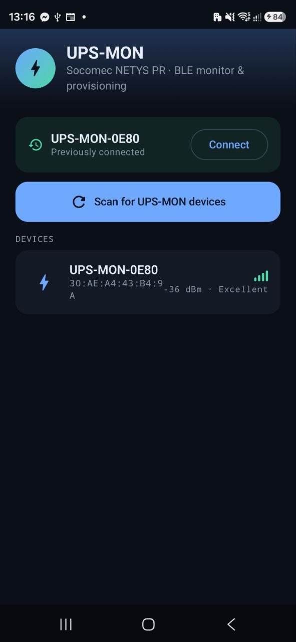
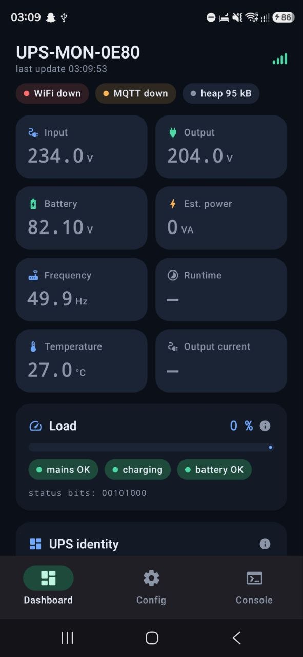
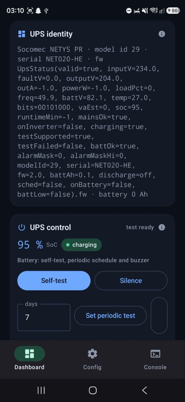
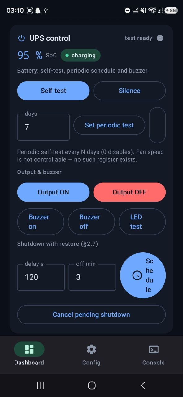
A Kotlin/Jetpack Compose application provides the BLE companion: device scanner, live dashboard (all JBus quantities, state chips, decoded alarm banners, UPS identity card), a config editor, and a raw JSON console for protocol work. The dashboard's control card mirrors the full command set — self-test, periodic test schedule, buzzer, LED test, output on/off with confirmation, and the shutdown-with-restore scheduler. Long device replies are reassembled from 20-byte BLE chunks; writes are chunked to MTU−5.
Security considerations
The design trades security for simplicity and is documented as such: the service-account key rests unencrypted in NVS and transits BLE unencrypted during provisioning; BLE provisioning itself is unauthenticated; and the push topic name derives from the device UUID, which must therefore be treated as semi-secret. Mitigation: a dedicated, throwaway Firebase project. Adequate for a homelab; not for production deployment.
Operational status
The system runs continuously: a 15 s polling cadence, nine MQTT attributes, 64 alarm bits under edge-triggered surveillance, and a single push topic on the phone. Register documentation, wiring diagrams, build instructions and the roadmap are maintained in the project repository.